Following on from last week, this time we did “blinky”: making the LED flash on the hardware. Once again, Tim kindly led us through this and supplied some additional LEDs and resistors so we could get multiple LEDs flashing.
The plan
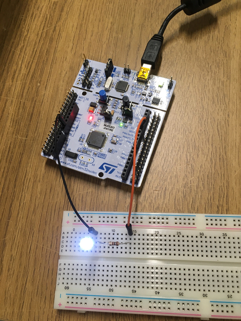
We’re working with the LED on the STM32 Nucleo-64 device, plus an external LED on a breadboard:
(There are more photos.)
In this session we:
- made sure everyone had caught up with last week;
- learned how to make the LED flash on the Nucleo; and
- made an external LED flash on a breadboard.
I should clarify a couple of things:
- the first “day”, and this second “day”, are just two hours we spend together; and
- what I’ve noted here is just what we did and chatted about as a group. I’ve taken some notes, and likely misinterpreted things, but Tim, Mark, Fran, Eric, James, and whoever else is around, are spotting things and getting stuff to happen.
Hardware abstraction layer
There’s a green LED on the Nucleo 64 that we can turn on or off. It goes by various names: “LED1”; “Arduino signal D13”, port “PA_5”; and as “LD2” printed on the board itself.
To access this peripheral we need to find and manipulate a corresponding memory-mapped register. The Rust Embedded Book describes various levels at which we can do this, from the most specific to the more abstract. We looked at the Hardware Abstraction Layer (HAL). This is a set of convenient traits, which then have hardware-specific implementations. This means we can write our code to one API and swap out different hardware-specific layers in our build.
We used stm32f4xx-hal, which implements the HAL traits in a “Peripheral Access Crate” (PAC) for our hardware. That boils down to adding this dependency to our project in Cargo.toml:
stm32f4xx-hal = { version = "0.6.0", features = ["stm32f411"]}
…where stm32f411 is the specific hardware we’re using,
and is a feature of the stm32f4xx-hal crate.
Code
The final code we ended up with blinked the on-board LED, and also blinked an external LED. It’s mostly a copy of delay-blinky.rs from the stm32f4xx-hal project.
#![no_main]
#![no_std]

extern crate panic_halt;

use cortex_m;
use cortex_m_rt::entry;

use crate::hal::{prelude::*, stm32};
use stm32f4xx_hal as hal;

#[entry]
fn main() -> ! {
    // Access the device peripherals (dp) and cortex peripherals (cp):
    if let (Some(dp), Some(cp)) = (
        stm32::Peripherals::take(),
        cortex_m::peripheral::Peripherals::take(),
    ) {
        // Set up the LED: it's connected to pin PA5 on the microcontroler
        let gpioa = dp.GPIOA.split();
        let mut led = gpioa.pa5.into_push_pull_output();

        // The external LED, on the next pin down:
        let mut xled = gpioa.pa6.into_push_pull_output();

        // Set up the system clock. We want to run at 48MHz for this one.
        let rcc = dp.RCC.constrain();
        let clocks = rcc.cfgr.sysclk(48.mhz()).freeze();

        // Create a delay abstraction based on SysTick
        let mut delay = hal::delay::Delay::new(cp.SYST, clocks);

        loop {
            led.set_high().unwrap();
            xled.set_low().unwrap();
            delay.delay_ms(1000_u32);
            led.set_low().unwrap();
            xled.set_high().unwrap();
            delay.delay_ms(1000_u32);
        }
    } else {
        panic!("failed to access peripherals");
    }
}
The rest of this post is walking down this code.
Peripherals
We’re making use of two sets of peripherals: the stm32-specific set for the LEDs,
and the basic cortex_m crate set to access a clock.
In both cases we do this by calling take().
There’s only one instance of peripherals: if you try to take it after taking it elsewhere in your code, you’ll get None back.
In our case we’re matching that we get Some both times, and we’d expect this as it’s the only place we’re trying to take the peripherals.
Next we get a mutable reference to the pin 5. We need mutable access because we’ll be changing the state by turning it on and off. Recall that the Rust compiler will keep track of this and ensure only one reference can do writing at any point.
The LED is inside the General Purpose I/O block:
let gpioa = dp.GPIOA.split();
let mut led = gpioa.pa5.into_push_pull_output();
The split() call gives us a structure containing the pins.
I don’t know why it’s called split, but once we’ve done that we can access the pins.
In this case it’s PA5 we’re after, and we want to treat it as an output.
I have a limited understanding of the “push pull” output mode. It seems that components are sensitive. You need to actively apply a voltage or actively ground it. Anything else (e.g., only removing a voltage) is “floating” and likely to cause the component to behave erratically. The “push pull” mode takes care of this by applying the voltage or grounding for us when we set the pin high or low.
So we have an led reference for the on-board LED.
We also then grab one down (PA6) for the external LED, called xled.
let mut xled = gpioa.pa6.into_push_pull_output();
Of course, this isn’t necessarily an LED. It’s whatever we connect on the end of the orange wire, which happens to be an LED:
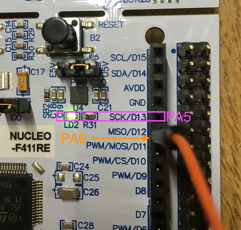
At first we connected the external LED into the pin 5 too, so the LEDs would flash in sync. We then moved down one pin and used the code above to alternate LEDs.
Timing
We’re going to alternate turning the two LEDs on and off every second. We’ll need a clock for that:
let rcc = dp.RCC.constrain();
let clocks = rcc.cfgr.sysclk(48.mhz()).freeze();
let mut delay = hal::delay::Delay::new(cp.SYST, clocks);
I don’t yet understand how these clocks are configured and used.
RCC is the “reset and clock controller” for the STM32 (there’s a presentation on this for related hardware),
and the freeze() call goes off and configures the clock source based on the configuration options we’ve selected.
The result, though, is that we can call delay.delay_ms(1000_u32).
On and off
We use the delay to sleep for a second after turning on (or off) an LED:
loop {
    led.set_high().unwrap();
    xled.set_low().unwrap();
    delay.delay_ms(1000_u32);

    led.set_low().unwrap();
    xled.set_high().unwrap();
    delay.delay_ms(1000_u32);
}
The value from set_high and set_low is Result, and I was wondering under what situations it would fail.
It seems that with this particular implementation it won’t fail.
The specific type is: Result<(), Infallible>.
That means we’ll get an Ok(Unit) (no value) on success, or an Err containing the Infallible type.
However, as Infallible has no values (rather like !), this signifies the result will always be Ok.
I assume there are plenty of other types of OutputPin could fail,
which is why we have a Result type from set_high and set_low.
Breadboard
The breadboard is set up as:
- a connection from either of the ground (GND) pins on the left of the board to the short leg of the LED;
- a connection from PIN 5 to the resistor; and
- the other end of the resistor to the long leg of the LED.
End result
Plugging in the hardware, starting openocd, and executing cargo run starts the program running.
For a while we were confused as to why GDB was pausing at breakpoints.
We eventually spotted that the breakpoints are configured in openocd.gdb,
and removing or commenting out the break expressions removed the breakpoints.
The result of running the code was:
I’ve pushed the project I used to a repository.