The one where we lit up the Xmas LEDs for the first time.
That was the original idea, after all:
- we buy a string of LED tree lights;
- learn a bit of embedded Rust; and
- “do something” with the string of lights.
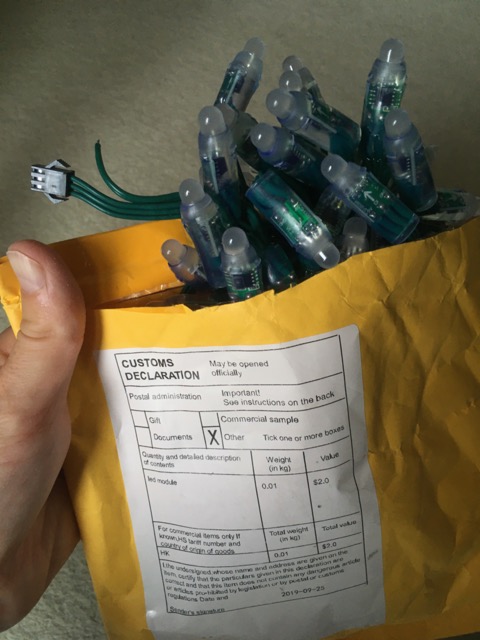
The lights are 50 individually addressable RGB LED. They arrived like this:
And at the end of the night we had this:
Here’s how we got there…
Hardware
The datasheet PDF says the lights are made up of a strip of WS2811 ICs. That is, WS2811 is the name of an integrated circuit from a company called Worldsemi. You can see the chip through the plastic of each light:
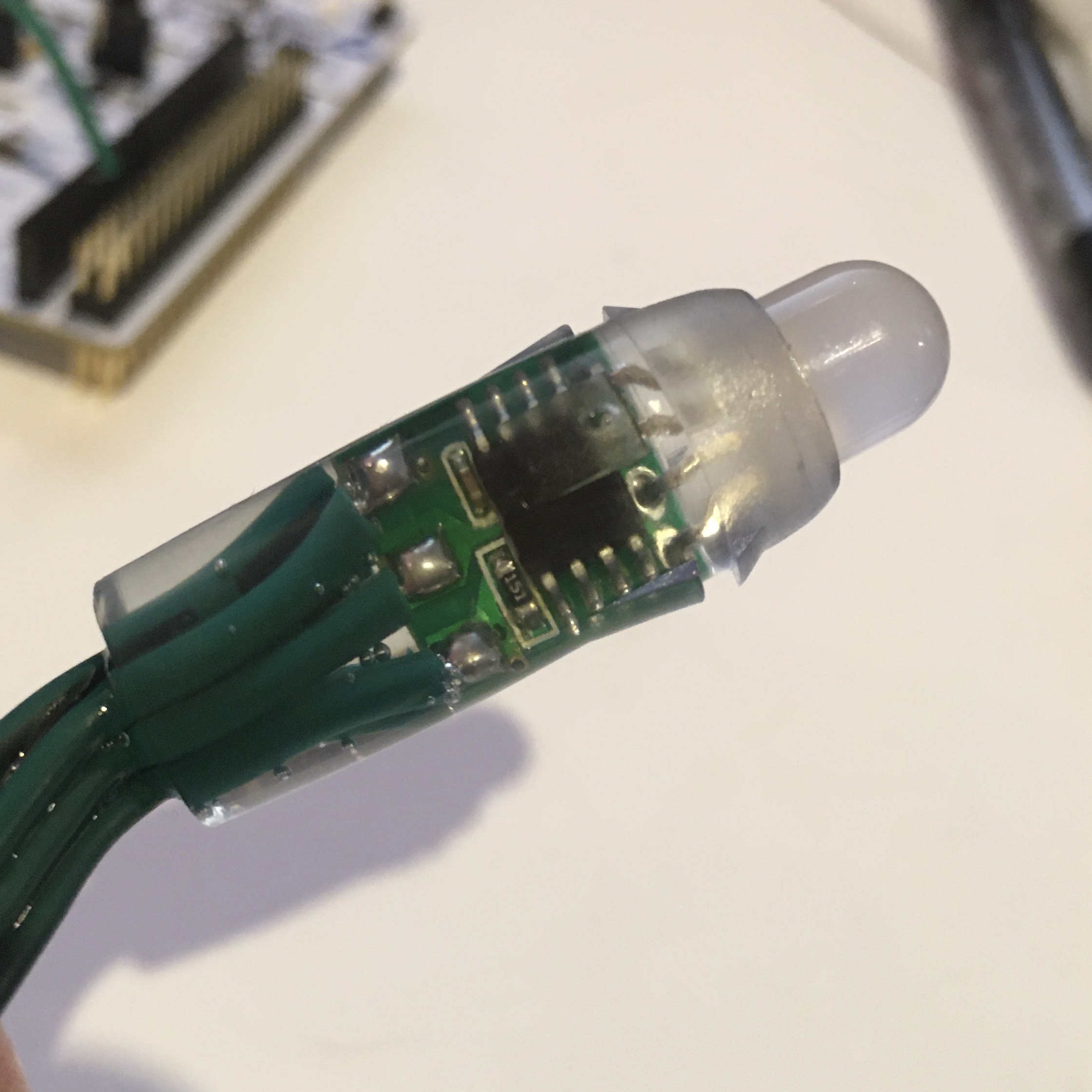
The chip is controlling (“driving”) an RGB LED. This package is chained together to give us 50 individually controllable lights. (There’s an outline of the details of how this works over at StackExchange.)
That means: we plug in one end to the Nucleo board, and set the RGB colour of each light.
Tim prepared a connector for us. It’s the red, white, and green wires you see here:
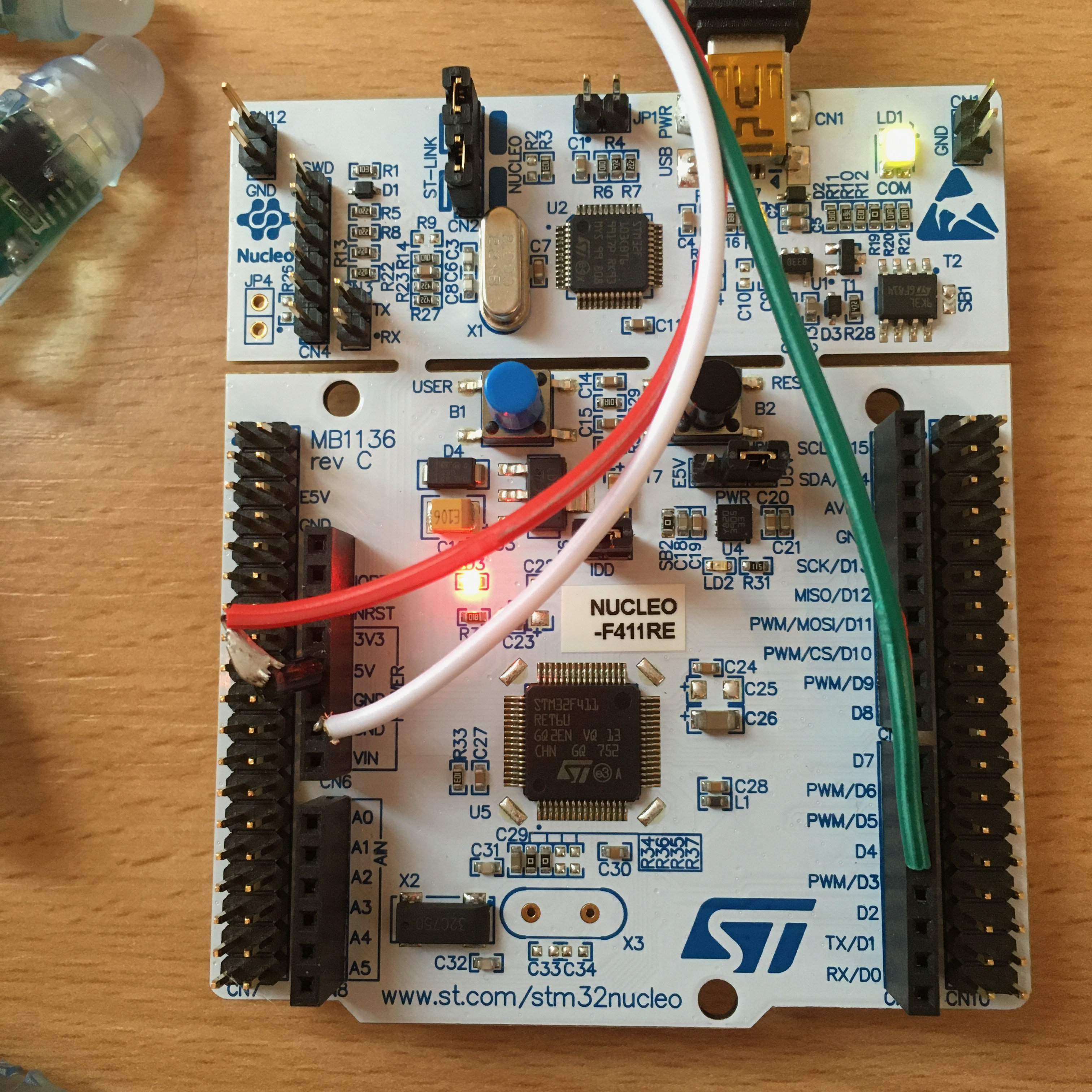
The red is connected to 5v, the white to ground, and the green to pin D4. There are a couple of complications:
Tim added a diode to the end of the red wire. This is to keep the voltage in-line with the spec for the chip.
Turning on all 50 LEDs will draw more current, which might overload the diode and maybe cause the USB power supply to shut down. So for now, we’re just turning on a few LEDs.
Tim has explained this in more details over in the group’s Matrix room.
Software
Tim also provided a project starting point using the smart-leds crate. The code blinks the first few LEDs in different colours. All I’ve done is take that code and move it into the RTFM framework, using a scheduler to turn the LEDs on and off. (Oh, I also changed the code to turn the LEDs blue, so I could tell which code I was running).
In Cargo.toml we’ve added:
smart-leds-trait = {version = "0.2.0"}
smart-leds = {version = "0.3.0"}
ws2812-spi = {version = "0.2.0"}
The ws2812-spi crate is a software driver compatible with smart-leds. That is, it lets us use the smart-leds API with the ws2812 hardware. The SPI part is the “Serial Peripheral Interface”, and there’s a very readable step through of SPI that’s worth a browse. I also enjoyed a video introduction I saw on YouTube.
I’ll walk down the new key parts of main.rs:
// Configure pins for SPI
let gpiob = dp.GPIOB.split();

// Master Out Slave In - pb5, Nucleo 64 pin d4
let mosi = gpiob.pb5.into_alternate_af5();
We’re using what’s labelled as D4 on the hardware for sending data.
It’s called pb5 in the GPIO B block.
Page 47 of the STM32F411RE PDF datasheet has a big table,
and shows that you need to select alternative function 5 to use PB4 for SPI1 MOSI.
Some of the details of SPI can be decided by hardware implementation. That means we configure SPI for the hardware we have. For example, we don’t have any data in from the slave (“no MISO”).
In our case, for these Xmas lights, the configuration is this:
// Serial clock:
let sck = gpiob.pb3.into_alternate_af5();

// SPI1, but we could have up to 5 Serial Peripheral Interfaces.
let spi = Spi::spi1(
    dp.SPI1,
    (sck, NoMiso, mosi),
    Mode {
        polarity: Polarity::IdleLow,
        phase: Phase::CaptureOnFirstTransition,
    },
    stm32f4xx_hal::time::KiloHertz(3000).into(),
    clocks,
);

let ws = Ws2812::new(spi);
The final line there is giving us something that implements the smart-led write function.
Here’s how we can use that:
let blue = RGB8 {
    b: 0xa0,
    g: 0,
    r: 0,
};

let data = [blue; NUM_LEDS];

ws.write(data.iter().cloned())
    .expect("Failed to write lights_on");
Running the code
As usual, with the hardware connected, we run openocd and cargo run to get into GDB. All the code is in a GitHub repository.
On thing we saw was an error from openocd:
Error: jtag status contains invalid mode value - communication failure
The fix was to hold down the reset button as we launched openocd.
The suspicion was that the last thing running had put the processor into some sleep state.
But with that running, the code blinks the first few LEDs every second.